
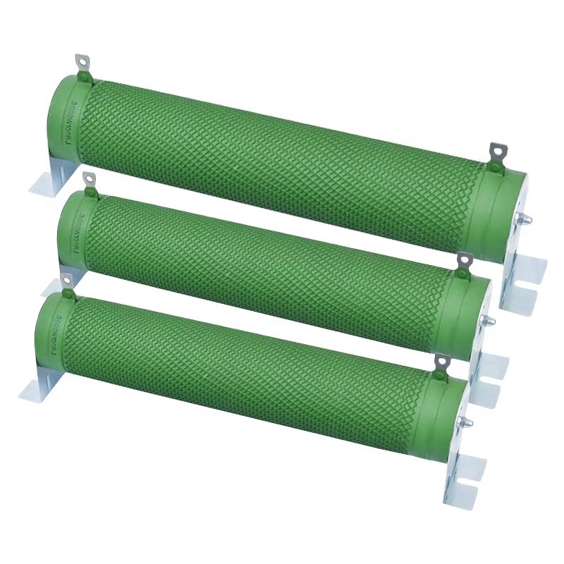
High-Power Corrugated Braking Resistor
Factory Direct · High-Power Corrugated Braking Resistor
Accurate resistance · Long-lasting · Stable performance — RX20 Series · 20W ~ 10000W
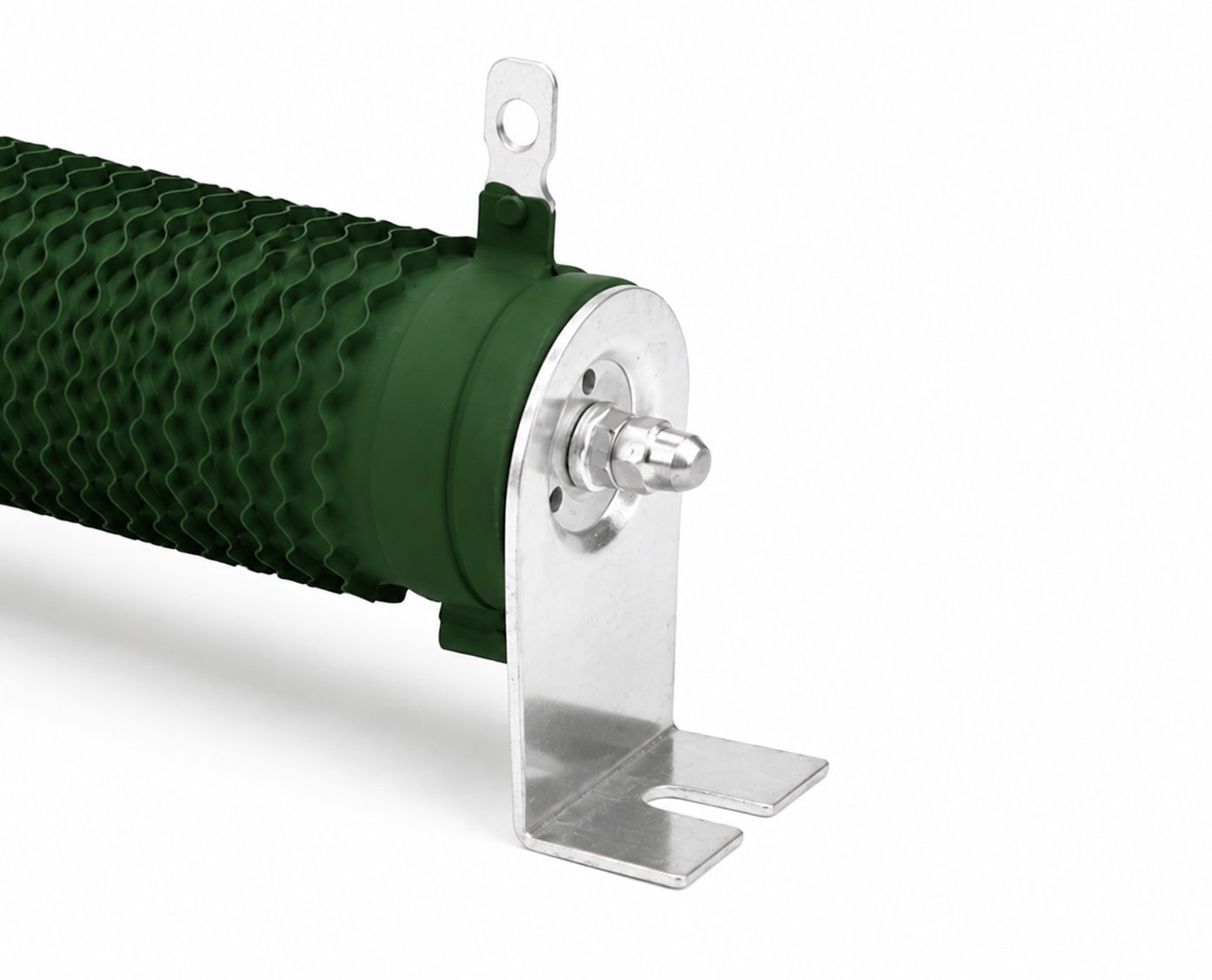
Vertical corrugated design enhances thermal dissipation and reduces parasitic inductance
The enclosure uses a vertical corrugated design with large surface area for smooth airflow, significantly enhancing thermal dissipation while reducing parasitic inductance — suitable forhigh-frequencybrakingandtransient surgesconditions. reinforced galvanized stainless-steel bracket, installationsecurestable — usesreinforced galvanized stainless-steel bracket, ensuresinstallationsecure / usestable; vibration-resistant / corrosion-resistant, suitable forindustrial cabinetsinternallong-termFixedinstallation.
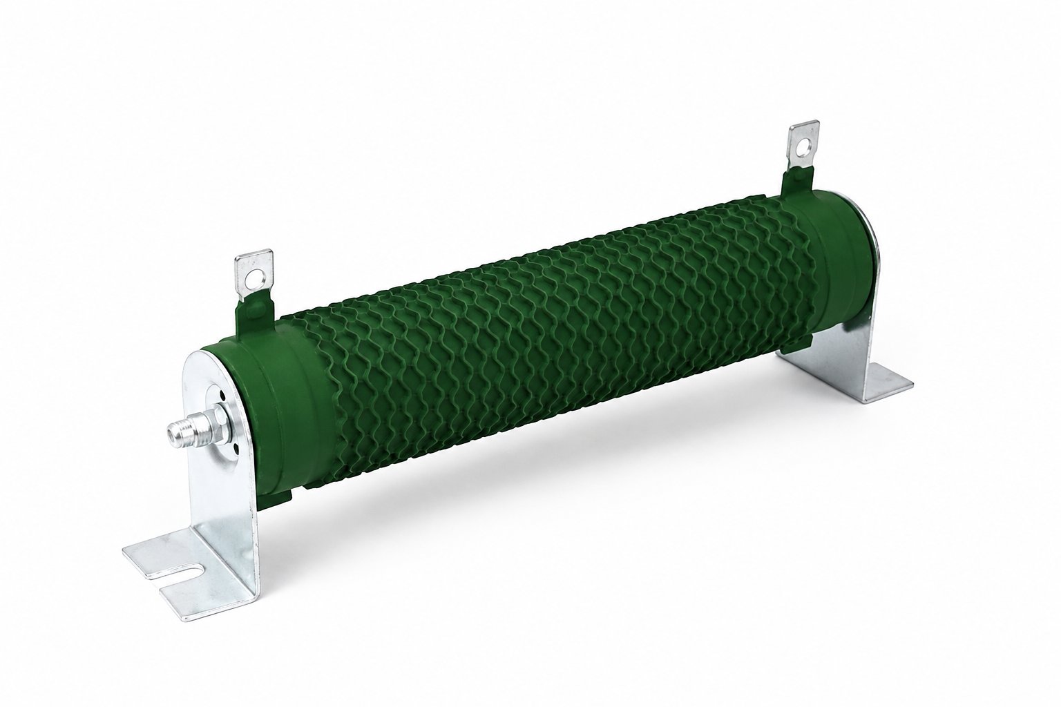
High-temp flame-retardant coating · long life · anti-oxidation
Carefully selected high-temperature flame-retardant coating extends service life and protection the wirewound element from oxidation, ensuring stable performance in high-temperature, humid and dusty harsh environmentsbelowlong-term stableoperation.
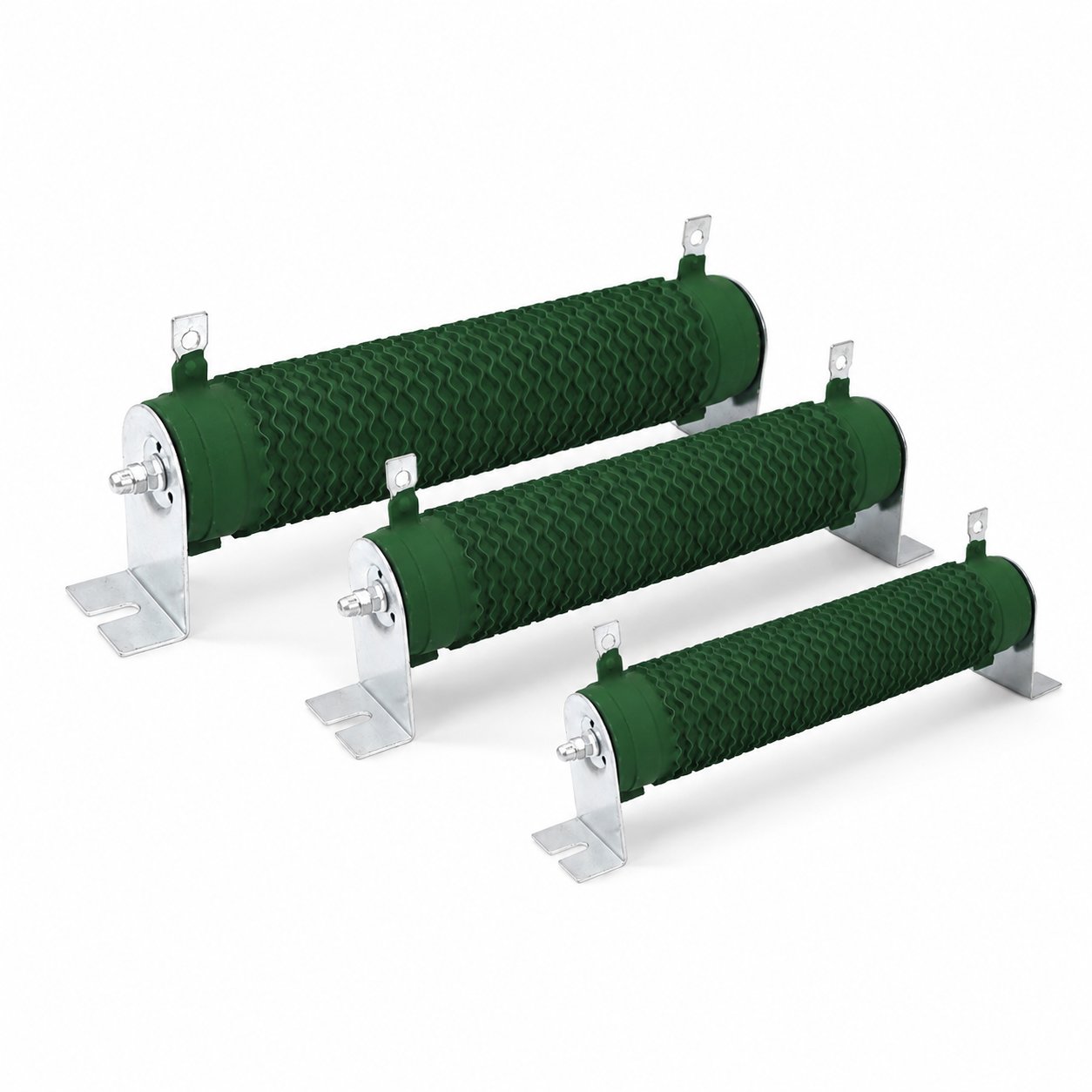
Multiple specs · flexible combinations · easy installation
Compact Size, high power, excellent stability and flexible architecture; can be combined in multiple configurations for easy installation — meets engineering needs for different power and resistance requirements.
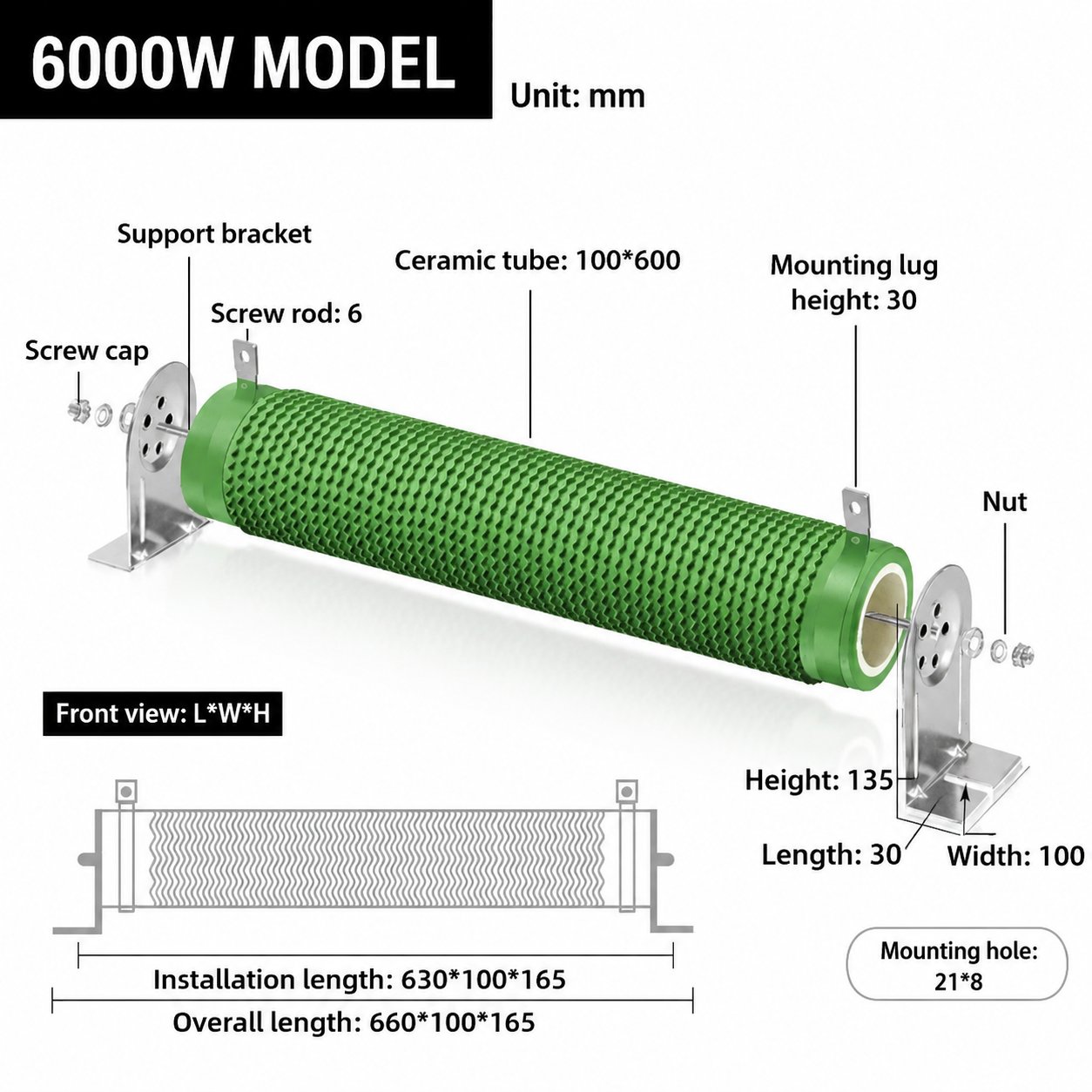
Dimensions
| Power Rating | Ceramic Tube Dimensions (mm) | Mounting Length (mm) | Total Length (mm) | Cross-section Dimensions (L×W×H mm) | Bracket Width (mm) | Bracket Height (mm) | Bracket Length (mm) | Clip-Ring Height (mm) | Threaded Rod | Mounting Hole (mm) |
|---|---|---|---|---|---|---|---|---|---|---|
| 50W | 27 × 90 | 125 | 145 | 125 × 27 × 65 | 27 | 43 | 20 | 20 | M6 | 14 × 6 |
| 100W | 27 × 170 | 182 | 210 | 182 × 27 × 65 | 27 | 43 | 20 | 20 | M6 | 14 × 6 |
| 150W | 27 × 215 | 245 | 265 | 245 × 27 × 65 | 27 | 43 | 20 | 20 | M6 | 14 × 6 |
| 200W | 27 × 267 | 289 | 305 | 289 × 27 × 65 | 27 | 43 | 20 | 20 | M6 | 14 × 6 |
| 300W | 40 × 200 | 220 | 240 | 220 × 40 × 85 | 40 | 59 | 25 | 25 | M6 | 9 × 6.5 |
| 400W | 40 × 267 | 287 | 307 | 287 × 40 × 85 | 40 | 59 | 25 | 25 | M6 | 9 × 6.5 |
| 500W | 50 × 300 | 330 | 360 | 330 × 50 × 98 | 50 | 68 | 30 | 30 | M6 | 21 × 8 |
| 600W | 50 × 330 | 360 | 390 | 360 × 50 × 98 | 50 | 68 | 30 | 30 | M6 | 21 × 8 |
| 800W | 70 × 300 | 330 | 360 | 330 × 70 × 130 | 70 | 100 | 30 | 30 | M6 | 21 × 8 |
| 1000W | 70 × 300 | 330 | 360 | 330 × 70 × 130 | 70 | 100 | 30 | 30 | M6 | 21 × 8 |
| 1500W | 60 × 430 | 460 | 490 | 460 × 60 × 128 | 60 | 98 | 30 | 30 | M6 | 21 × 8 |
| 2000W | 60 × 510 | 540 | 570 | 540 × 60 × 130 | 60 | 98 | 30 | 30 | M6 | 21 × 8 |
| 2500W | 70 × 430 | 460 | 490 | 460 × 70 × 130 | 70 | 100 | 30 | 30 | M6 | 21 × 8 |
| 3000W | 80 × 430 | 460 | 490 | 460 × 80 × 158 | 80 | 128 | 30 | 30 | M6 | 21 × 8 |
| 4000W | 100 × 430 | 460 | 490 | 460 × 100 × 165 | 100 | 135 | 30 | 30 | M6 | 21 × 8 |
| 5000W | 100 × 500 | 530 | 560 | 530 × 100 × 165 | 100 | 135 | 30 | 30 | M6 | 21 × 8 |
| 6000W | 100 × 600 | 630 | 660 | 630 × 100 × 165 | 100 | 135 | 30 | 30 | M6 | 21 × 8 |
Electrical Characteristics
| Test Item | Test Condition | Performance |
|---|---|---|
| TCR Temperature Coefficient | Measure resistance at room temperature and at room temperature +100°C, then calculate resistance change per °C | ±300 ppm/℃ |
| Short Time Overload | Apply voltage corresponding to 10× rated power (√10PR) or maximum operating voltage (whichever is lower) for 5 seconds | ΔR ≤ ±(2%R0+0.05Ω) |
| Resistance to Soldering Heat | Dip in solder bath at 350±10°C for 2~3 seconds | ΔR ≤ ±(1%R0+0.05Ω) |
| Solderability | Dip in solder bath at 260±5°C for 2~3 seconds | Solder coverage ≥95% |
| Temperature Cycling | 30 min at -55°C → 10~15 min at +25°C → 30 min at +275°C, 5 cycles | ΔR ≤ ±(1%R0+0.05Ω) |
| Load Life in Humidity | 40±2°C and 90~95% RH chamber; apply rated or maximum operating voltage for 1000h (1.5h ON / 0.5h OFF) | ΔR ≤ ±(5%R0+0.05Ω) |
| Load Life in Heat | 70±2°C chamber; apply rated or maximum operating voltage for 1000h (1.5h ON / 0.5h OFF) | ΔR ≤ ±(5%R0+0.05Ω) |
| terminal Strength | Pull: 10N | ΔR ≤ ±(2%R0+0.1Ω) |
| Vibration | Frequency 10~55Hz, amplitude 0.75mm, 6 hours | ΔR ≤ ±(2%R0+0.1Ω) |
| Nonflammability | Apply 5×, 10×, 16× rated power AC load for 5 minutes | No visible flame |
48-Hour Free Samples
Free samples for standard parts — shipped within 2 business days.
Custom to Drawing
Drawing- and spec-based customization. Engineer responds within 24 hours.
Volume Discounts
Factory-direct supply at scale — direct manufacturer pricing.
Worry-Free After-Sales
12-month warranty with a dedicated team for technical issues.
Customization Process
Contact Us
Reach out, learn about our products, share your needs
Specify Requirements
Discuss specifications with our team
Get a Quote
We send pricing and proposal
Place Order
Confirm order and payment
Production
Manufacturing and quality inspection
Ship
Pack and ship the goods
Delivery
Confirm receipt and feedback
Other products in the High-Power Resistors series
View all High-Power Resistors →
Frequently asked questions
Is a free sample available for this product?
What is the minimum order quantity?
How long is the warranty?
What payment terms do you accept?
Can I order this product in custom dimensions or values?
How do I get a datasheet or 3D model?
Sample Request
Standard samples are provided free of charge in reasonable quantities (shipped within 2–3 business days). Custom samples are delivered within 2–4 weeks. Please use the form on the right to tell us:
- Company and contact details
- Target part number or key specs (power / resistance / package)
- Application scenario and estimated annual volume
- Shipping address and expected delivery date